|
Introduction
The Tandy
Color Computer was introduced with two analogue joystick ports. The
analogue joysticks provided a variable voltage to an internal
Analogue-to-Digital converter (ADC) circuit which
translates these voltages into a 6-bit value in the range of 0 to
63.
 In
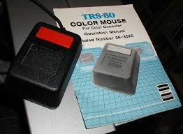
1984, a mouse was released and sold by Radio Shack.
Like the joysticks, it also was an analogue device which mimicked
the joystick's operation using two variable resistors for the X and
Y axis. The resolution of the mouse was the same as the joystick
since they were both tied to the same 6-bit ADC circuit within the
Color Computer. In
1984, a mouse was released and sold by Radio Shack.
Like the joysticks, it also was an analogue device which mimicked
the joystick's operation using two variable resistors for the X and
Y axis. The resolution of the mouse was the same as the joystick
since they were both tied to the same 6-bit ADC circuit within the
Color Computer.
Unfortunately, the 6-bit precision of the ADC meant the
joysticks and mice could only address a 64 x 64 area and this
was too low to represent every pixel position of the original Color
Computer's high resolution 256 x 192 screen.
Furthermore, scaling the joystick to match the screen
resolution produced a jumpy and innacurate mouse movement that
was unable to effectively represent every screen pixel
accurately.
When the
Mac-like paint program CoCoMax was released in 1985, it
came bundled with a rompak style cartridge containing an 8-bit ADC
chip that gave a resolution of 256 points. This worked very well but
unfortunately, CoCoMax was the only software that supported
it.
In 1986,
Tandy released the Color Computer 3 with a new 320 x 225 screen in
16 colors and a maximum 640 x 225 screen in 4 colors. The Color
Computer's 6-bit ADC resolution was too low and another
solution had to be found.
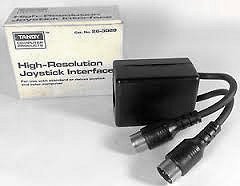 A
new hardware interface was required that improved on the low 6-bit
resolution of the ADC and so Radio Shack released the
High-Resolution Interface in 1987. This device was designed by the
famous
Steve Bjork and was manufuctured and sold by Radio Shack. This
interface used a voltage pump to create a rise in voltage that is
compared against the two pots of the joystick. The timing of the
voltage rising to match the joystick is what creates the value of the
joystick position. A
new hardware interface was required that improved on the low 6-bit
resolution of the ADC and so Radio Shack released the
High-Resolution Interface in 1987. This device was designed by the
famous
Steve Bjork and was manufuctured and sold by Radio Shack. This
interface used a voltage pump to create a rise in voltage that is
compared against the two pots of the joystick. The timing of the
voltage rising to match the joystick is what creates the value of the
joystick position.
A third high
resolution mouse option was later released by Diecom which
utilized a PC style serial mouse and connected to the Color
Computer's serial port. This was sold with their drawing and paint
software, The Rat.
Common with
all these high resolution options was that they needed a dedicated
piece of hardware to replace the limitations of the Color Computer's
built in ADC circuit.
"You built a Hi-Res Interface... out of a
DeLorean!?"
Back in the early 90's, John Kowalski had an idea
for a new way of reading the Color Computer 3 joystick ports that
could extrapolate additional information between the 6-bit
sample points of the built-in ADC. He theorized that the voltage
applied to the Digital-to-Analogue converter (DAC) which worked with
the ADC didn't merely jump instantaneously between each of the 6-bit
points but transitioned as a rapid voltage slide and that
with very fast and syncronized software, extra readings could be had
that would provide a higher level of precision.
But at that time, he didn't have any project planned to
use such a feature and moved on to other groundbreaking software
projects of which John has become famous for.
In 2007, John created the groundbreaking feat
of converting the Z-80 based Donkey Kong original arcade
code to 6809 and emulating the functions of the original arcade
hardware on a stock standard CoCo3. In 2015, he improved it by
making it slightly faster and added 6 extra levels to the
original game. On completion of the project, his thoughts of
the new hi-res software routines returned. He mentioned his idea to
me and I immediately said "let's do it!".
I've worked with John in the past on some of his
brilliant ideas. Firstly, he helped me to understand his
groudbreaking Gloom 3D algorithm which I used in my game
Gate Crasher, the first true solid 3D complete game for the
Color Computer 3. He was very instrumental in explaining the math
involved. As kryptonite is
to Superman, math is to me. I hate math and his patience and clear
explanations helped me to complete Gate Crasher in 2000. LINK
We later worked on another of his ideas we titled
DigiWiper which primarily involved the removal of
the Macrovision encoding on commercial video tapes... for the
purpose of creating backups of our original tape investment! As a
bonus we were also able to add realtime video transitions
between the dubbing of video tapes. LINK
So, I had no hesitation in listening to his latest
"crazy idea" and I began coding to see if it was indeed
possible.
How the ADC works
The real work when converting any analogue voltage to a
digital reading with the Color Computer is actually done using
the DAC (Digital-to-Analogue) converter. To understand how the ADC
(Analogue-to-Digital) circuit works, we must understand how the DAC
works.
In simple terms, the DAC accepts data from the computer
and converts it to an analogue voltage. Although the computer's data
bus is 8-bit, the input to the DAC is only 6-bits.
This represents a value from 0 to 63 or 64 individual
voltage steps as output from the DAC. This is also how the 64 levels
of volume is derived when the DAC output is diverted and used for
sound generation.
In order to get a digital reading from the joystick
port, the output of the DAC is fed into an input of a
voltage comparator. At the same time, the voltage from
the joystick or mouse is fed into a second input of the voltage
comparator. This voltage comparator compares the two input
voltages and sets an output high or low to indicate the
difference. Software running on the Color Computer can read the
comparator output and determine if the DAC voltage needs to be
raised or lowered to attempt to match the joystick port voltage.
This test is repeated until it locates the DAC voltage value which
coincides with the incoming voltage. Through a process of succesive
approximation, an accurate ADC value can be
found.
This is the first stage of reading the joystick port that
derives the normal 6-bit joystick port reading.
For the rest of the explantion of how we go beyond this
6-bit limitation, let's assume that we scanned the joystick
port and found a value of 32 with a joystick at
midpoint.
Deep scanning "the
abyss"
Now to test John's theory and see if we can pull
additional readings from points in between any of the 64 ADC points.
In this example we want to scan between 31 and 32 as well as
between 32 and 33.
The first step is to create several delay points that
trigger from the moment we set a new DAC voltage level up and down 1
unit from the current. For example, with a 6-bit DAC reading of 32,
we then need to switch the DAC voltage to 31 if we want to scan
below. If we want to scan above 32, then switch to 33.
The moment we set the DAC
to this new value, we need to immediately begin our
timings.
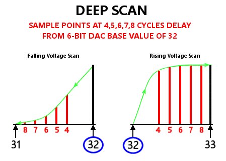 Multiple scans are then made at varying time intervals
with the first interval starting at a 4 cycle delay from the moment
the new voltage point is set. More voltage points were scanned
at 1 CPU clock cycle iterations after the intial 4
cycles. Multiple scans are then made at varying time intervals
with the first interval starting at a 4 cycle delay from the moment
the new voltage point is set. More voltage points were scanned
at 1 CPU clock cycle iterations after the intial 4
cycles.
Why 4 cycles for the first delay
point?
Because 4 cycles is the shortest number of CPU
cycles to write and read the data to the DAC (with a stock
68B09 CPU set to 1.79Mhz). The remaining points then add to this. In
the end we wound up with 5 time intervals down from the base
voltage and another 5 time intervals up from the base voltage; i.e.
10 additional sampling points.
You can see from the graph on the right that the 4 cycle
delay creates a period where we cannot obtain data.
Now to see what we CAN find!
We did many multiple scans, graphing the results and
displaying them in realtime while we moved the joystick ever so
slightly. The results looked promising and we discovered that the
clearest and most accurate readings were to be found at the 4 and 5
cycle delay when the voltage was dropped down from the base setting.
The weight of the readings varied the longer the delay from
the base voltage but even the poor readings provide additional
information that we could use.
I
found that the readings when the voltage was raised from the
base were not being detected as well as the readings when the
voltage was lowered from the base. I suspect that a rising
voltage happens much faster as more voltage is injected via the DAC,
but a falling voltage is slower due to capacitance in the DAC
circuits dampening the voltage decay. The faster shift of the
rising voltage was too fast for the slow 6809 to detect properly and
gives a very narrow window of data. These are not given very much
weight but even these contribute to the total reading and
help fill in a couple of the gaps.
Fuzzy Logic
After many days and weeks of experimenting and analysing,
John applied his amazing skills of math and data analysis to average
and weight all the results to eventually obtain a reasonably
accurate 15-bit total joystick port reading. Quite amazing when you
factor in the general noisiness of a 30 year old variable resistance
device such as the Tandy joystick or mouse, not to mention the
electromagnetic interferance from surrounding electronics. It's
amazing to be able to piece together the little scattered bits of
data and reassemble them into a combined whole reading. The noise in
the readings also help make our multiple readings randomize a bit
and by averaging out the roughness, we get a non-noisy reading with
even higher resolution than otherwise possible.
A
further massage of the obtained data to apply some extra smoothing
and scaling to match the Color Computer's screen
resolutions and we had a working Hi-Res joystick interface
driver!
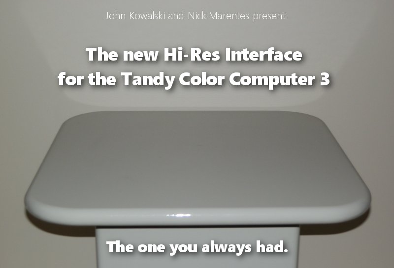
The Hi-Res interface you always
had!
 I
created two programs to demonstrate the driver. The first
DEMO320 places a mouse pointer on a 320 x 200 high resolution
screen that can be moved smoothly across the entire area. I also
added the function to scribble on the screen when the mouse
or joystick button is held down while the mouse pointer is moved. I
created two programs to demonstrate the driver. The first
DEMO320 places a mouse pointer on a 320 x 200 high resolution
screen that can be moved smoothly across the entire area. I also
added the function to scribble on the screen when the mouse
or joystick button is held down while the mouse pointer is moved.
For fun, I placed a screenshot of Greg Miller's and
Eric Gavriluk's insanely brilliant ColorMax Deluxe paint
program as a background to highlight a potential use for such a
driver.
Maybe this driver can be used to replace the Hi-Res
Interface driver built into ColorMax Deluxe?
 The
second demonstration DEMO640 demonstrates the driver
operating in 640 x 225 and I have placed a 'mockup
only' background of an SDC Disk Management utility that I
was toying with. It utilizes the highest resolution graphics mode
the CoCo3 can produce and was an ideal candidate to see how well the
new driver can operate at this resolution. I even provide the scribble mode from DEMO320
to see the fine linework that can be produced. The
second demonstration DEMO640 demonstrates the driver
operating in 640 x 225 and I have placed a 'mockup
only' background of an SDC Disk Management utility that I
was toying with. It utilizes the highest resolution graphics mode
the CoCo3 can produce and was an ideal candidate to see how well the
new driver can operate at this resolution. I even provide the scribble mode from DEMO320
to see the fine linework that can be produced.
Surprisingly, the mouse precision is quite smooth
with just a few hints of imprecision noticeable when drawing. As for
mouse positioning, it's just about perfect
and quite amazing
that it's operating without any hardware Hi-res Interface... using
only the CoCo3's built in 6-bit ADC/DAC!
You can try both of these demos for yourself by
downloading the distribution disk in DSK format at the bottom of
this page. To start the
demos, type RUN "DEMO320" or
RUN"DEMO640".
This driver code works on a real
CoCo3. Software emulators such as VCC and MAME do not emulate the
original ADC/DAC characteristics required for this to work properly
at full precision. They will work but only as a 64 x 64 resolution
mouse. You will be amazed by how well the averaging and smoothing
software is working to give the appearance of more
precision.
This demo clearly demonstrates the success of this
project and is yet another entry that John Kowalski can cross
off the list of things that are impossible to do on the Tandy
Color Computer.
Use it in your BASIC
programs!
Robert Gault has joined us and added support for BASIC
programs by adding additional scaling options supporting
various screen resolutions as well as optimisations in speed. It's
now possible to use a PMODE 4 (256 x 192), HSCREEN 2 (320 x
192/200/225) and HSCREEN 4 (640 x 192/200/225) screen
resolution.
He has created a demonstration in BASIC that calls the
high resolution joystick subroutine and places a
mouse pointer over the screen. His program is available on the distribution DSK and can
be started by entering RUN"DEMOBAS". To interface your program to the NEWJOY subroutine
|
| Clear memory above &H7000 and load the
NEWJOY subroutine. |
NEWJOY loads from location &H7000 |
| Set the desired screen scaling from BASIC by
POKE'ing to locations &H7004 and &H7005. |
XSCALE: POKE &H7004,number
(1=256 2=320 3=640)
YSCALE: POKE
&H7005,number (1=192 2=200
3=225) |
| Call the NEWJOY subroutine. |
EXEC &H7006 |
| Read the X-value (XVAL) and Y-value (YVAL) returned by
PEEK'ing at locations &H7000 to &H7003. |
XVAL:
PEEK(&H7000)*256+PEEK(&H7001)
YVAL:
PEEK(&H7002)*256+PEEK(&H7003) |
As an added bonus,
Robert's program also patches BASIC to operate in graphics screens
of 200 and 225 lines. Yet another undocumented feature that was
possible back in 1986. I will be providing details of this on a
future web page.
Use it in your Assembly Language
programs!
For anyone interested in implementing this software-only
Hi-Res joystick driver into their application or even patching an
existing program to remove the reliance on the Hi-Res Interface
hardware, the source code is provided on the distribution disk in EDTASM6309
format. A text file is also provided for importing into other
assemblers (see below).
Prior to calling the routine, you must select the desired
joystick port and axis by setting the appropriate bits in the Color
Computer's Analog Multiplexer.
|
$FF03 |
$FF01 |
SOUND SOURCE |
JOYSTICK |
|
BIT 3 OFF
BIT 3 OFF
BIT
3 ON
BIT 3 ON |
BIT 3 OFF
BIT 3 ON
BIT
3 OFF
BIT 3 ON |
DAC
CASSETTE
CARTRIDGE
NO
SOUND |
RIGHT X
RIGHT Y
LEFT
X
LEFT Y |
Then, if you wish to sample the X axis of the joystick or
mouse, load the location AXIS with a 0 and load register Y to
point to #DACX prior to calling the routine (READ). This
will return a 16 bit value in XVAL, scaled to the XSCALE
setting you chose.
If you wish to sample
the Y axis of the joystick or mouse, load the
location AXIS with a 1 and load register Y to point to #DACY
prior to calling the routine (READ). This will return a 16 bit value
in YVAL, scaled to the YSCALE setting you
chose.
You will be calling the routine once for each axis
for each joystick or mouse you wish to read. Below is the code I
used to call the high resolution routine in the
demo.
LDA
$FF01 ;SET JOYSTICK
X
ANDA #247 ;RESET
BIT3
STA
$FF01
LDY
#DACX ;SET 15 BIT
SAMPLE POINTER
CLR
AXIS ;SET X
SCALING
JSR
READ ;GET
JOYSTICK X AXIS
STX
XVAL ;SAVE
RESULT
LDA
$FF01 ;SET JOYSTICK Y
AXIS
ORA #8 ;SET
BIT3
STA
$FF01
LDY
#DACY ;SET 15 BIT
SAMPLE POINTER
INC
AXIS ;SET Y
SCALING
JSR
READ ;GET
JOYSTICK Y AXIS
STX
YVAL ;SAVE
RESULT
You can
delete the scaling parts from the NEWJOY source code that you don't
require to make the routine occupy less
memory.
|
We've achieved what we had hoped to achieve... to
prove that the Color Computer 3 always could read the joystick
in high resolution. We wish that this had been done
back in 1986 when the Color Computer 3 was first introduced
then maybe there would have been more mouse driven programs
released. Hopefully, we will see new programs utilising this
driver and even some old favorites patched to use
it.
Download
the DISTRIBUTION
DSK
View the NEWJOY
subroutine SOURCE CODE
NOTE: The demos
provided on the Distribution Disk only work correctly on real
CoCo3 hardware. The VCC and MESS emulators do not emulate the
voltage characteristics obtained from the DAC/ADC circuits
found on real CoCo3
hardware. |
|